
Low-Speed Worm Gear Motors: Ratios, Efficiency and Selection
A low-speed worm gear motor should be specified from the output torque backwards, not from the output speed forwards. The ratio needed is a consequence of the torque the mechanism demands, and the speed that results is a consequence of the ratio together with the motor's speed. Choosing the ratio first because a published figure such as a few rpm looks plausible is how designs end up with a motor that cannot turn the load, or with a gearbox that is larger than the machine can hold.
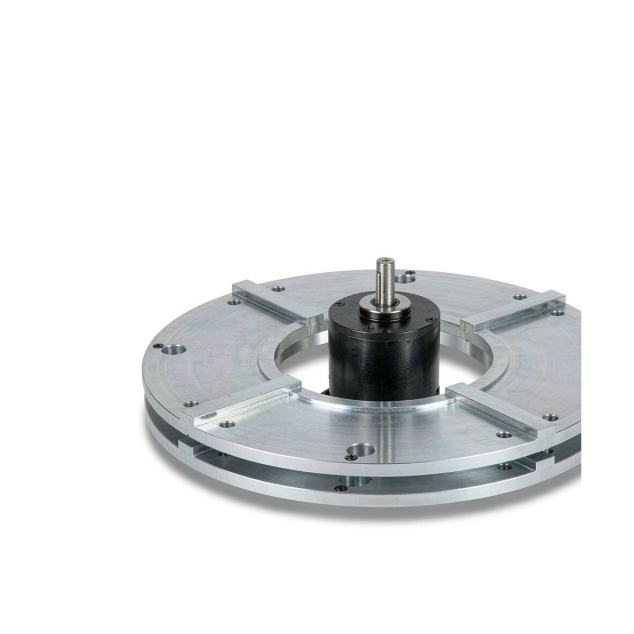
Low-speed worm gear motor driving a rotating turntable platform, showing high reduction and slow output motion, on a white background.
This article sets out that reverse order, works through the ratio and efficiency arithmetic with a labelled illustrative example, and explains how duty cycle and temperature interact with low-speed running. It ends with the requirement template that lets a supplier quote against your numbers rather than against a catalogue approximation.
Hofon's DC worm gear motor series is organised by ratio and frame size, and the selection questions below are the ones that come up most often in matching a unit to a slow mechanism.
Start from torque, not from speed
The output speed is the easiest number to describe and the least useful one to start from, because many ratios can produce the same output speed from different motors. Output torque is the constraint that actually eliminates options: it depends on the load, the friction in the mechanism, the acceleration required, and any safety factor the application demands. Once that number is fixed, the rest of the chain follows.
1. State the required output torque, including the peak value during acceleration and any margin the application needs.
2. State the output speed range the mechanism can tolerate, not a single preferred figure.
3. Divide the motor's rated speed by the target output speed to get the ratio, then round to an available ratio in the direction that keeps torque adequate.
4. Divide the required output torque by the ratio and by the gearbox efficiency to get the torque the motor itself must produce.
5. Check that the motor can produce that torque at the speed it will be running, and that the resulting current is within what the supply and the winding can handle.
6. Check the duty cycle against the thermal limit of both motor and gearbox.
Any step in that chain can move the answer, which is why a request phrased as an output speed alone usually comes back with a question or two.
Worm gear ratio, output speed and the arithmetic in between
The relationship itself is simple. Output speed equals motor speed divided by the ratio, and output torque equals motor torque multiplied by the ratio and by the efficiency of the reduction. Low output speed therefore comes from a high ratio, and the high ratio is what makes the output torque large enough to be interesting.
An illustrative calculation makes the shape of it clear. Suppose a mechanism needs about 1.5 N·m at its output and can accept roughly 6 rpm. A motor running at about 1,200 rpm would need a ratio near 200:1 to land at 6 rpm. If the reduction were assumed to be perfectly efficient, the motor would have to supply about 7.5 mN·m of torque. In practice the losses in the reduction mean the motor must supply more than that, and the next section shows how much more the assumption matters.
The numbers in that example are chosen to show the method; they are not a product specification. The point is that the ratio and the motor-side torque are both derived quantities, and both are sensitive to the efficiency figure used.
Why efficiency changes the answer
Worm reductions work by sliding contact, so a portion of the input power becomes heat instead of output torque. The practical effect is that the motor must produce more torque than a naive division would suggest: the required motor torque is the output torque divided by the ratio and then divided again by the efficiency.
Two consequences follow for low-speed designs. First, small differences in the assumed efficiency translate into visible differences in the motor required, so the efficiency figure should come from the supplier rather than from a rule of thumb. Second, because the loss appears as heat in the gearbox, a low-speed high-ratio unit that runs continuously has a thermal limit that a low-ratio unit reaching the same output speed does not have. Where the duty is continuous, the ratio that looks most elegant on paper may be the one that overheats.
Self-locking is a selection input, not a free feature
At high ratios the reduction often resists being back-driven, which is attractive for mechanisms that must hold a position with the power off. It should be treated as an input to selection rather than an assumption: whether a particular unit back-drives depends on its lead angle, on lubricant and temperature, and on whether the load arrives steadily or as shock. If holding a load is a safety-related requirement, ask for it explicitly and expect the answer to include a margin rather than a yes.
The complementary question matters just as much: if the mechanism is ever moved by hand during setup, or if the load is expected to be lowered under its own weight, a self-locking reduction will resist that too. Deciding which direction should be free is part of the specification.
Duty cycle, temperature and low-speed running
Low speed does not mean gentle duty. A motor running slowly against a heavy load can draw close to its stall current for long periods, which heats the winding far more than intermittent operation at higher speed does. Meanwhile the gearbox is generating its own losses at the sliding contact and dissipating them through a housing with no airflow around it.
The specification therefore needs to state how long the unit runs and how long it rests, and what ambient temperature the machine sees in service. A unit qualified for short bursts cannot be assumed to survive continuous operation merely because its output speed is low; the thermal question is about current and time, not about rpm.
Lubrication and noise at low speed
Two further characteristics show up in slow mechanisms. The sliding contact depends on the lubricant being present at the mesh, so a unit expected to run for its life without service needs a sealed lubricant charge and should be specified as such. And at low output speeds the tooth contact is slow and continuous rather than impulsive, so noise usually comes from the motor and the mesh together; where a product is used near people, the acceptable sound level belongs in the requirement as a number, not as an impression.
The requirement template to send a supplier
Item | What to state | Why it matters |
Supply voltage | Nominal and the range it may vary over | Sets the current needed for a given torque |
Output torque | Continuous and peak, with any safety margin | The constraint that drives ratio selection |
Output speed | Target and acceptable range | Confirms the ratio after torque is fixed |
Duty cycle | Run time, rest time, starts per hour | Decides the thermal limit for both motor and gearbox |
Ambient and mounting | Temperature, orientation, how heat can leave | Affects both life and available torque |
Shaft and load | Radial and axial loads, shaft features | Determines bearings and output interface |
Holding requirement | Whether the load must be held unpowered | Decides whether self-locking is needed or must be avoided |
Acoustic target | A decibel figure at a stated distance | Removes ambiguity about what quiet means |
A low-speed worm gear motor is specified by working backwards: fix the torque, derive the ratio, correct for efficiency, then check the thermal and holding requirements against the real duty cycle. Done in that order, the output speed that appears on the finished drawing is a result rather than a hope.
Send the table above with your values filled in and we will quote against your low-speed requirement rather than against a catalogue figure.