
What Is a DC Motor? Definition, Construction and How It Differs
A DC motor is an electrical machine that converts direct current into continuous rotation. Its definition rests on three things working together: a magnetic field that is stationary with respect to the housing, a current-carrying winding on the rotating part, and a commutating element that repeatedly reverses the current in that winding so the resulting torque keeps pushing the rotor the same way round instead of balancing out. Remove the commutating element and the rotor would simply settle into alignment and stop.
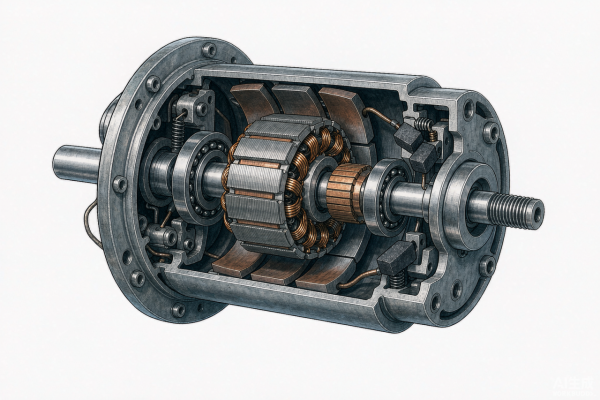
Cutaway view of a DC motor showing the stator magnets, slotted armature winding, commutator and carbon brushes
That definition matters because it separates two things that are often merged in casual use. A DC motor is defined by its power source, direct current, and by the presence of a commutating mechanism — mechanical in a brushed motor, electronic in a brushless one. A motor that runs from a DC supply but is built and controlled like an AC machine, or a motor whose position is set by a driver rather than by commutation, does not fit the same definition, and the difference shows up in how it behaves at low speed and how it is specified.
This article gives the definition, breaks the machine into its main parts, explains where the torque comes from in qualitative terms, and sets out how brushed, brushless and permanent-magnet types differ.
Hofon manufactures micro DC motors and a DC motor range covering both brushed and brushless construction, which is why the definition below is written to cover both.
A working definition: the four parts of a DC motor
Strip away the variants and four functional blocks remain. Each one has a job, and each one is a place where a specification can go wrong.
1. The stator field. Either a set of permanent magnets or a field winding, mounted in the housing, providing the magnetic field the rotor works against. Permanent-magnet construction is the norm in small motors because it removes the field winding losses entirely.
2. The rotor or armature. The rotating member carrying the winding that current flows through. In a brushed motor the winding sits in slots in a laminated core; in a brushless motor the magnets rotate and the windings stay in the stator.
3. The commutating element. In a brushed motor this is the commutator and brush assembly, which mechanically switches the winding as the rotor turns. In a brushless motor an electronic drive reads rotor position and switches the stator phases instead.
4. Bearings, shaft and end caps. The mechanical interface that holds the rotor in place, sets the axial and radial load the motor can take, and decides how much of the electrical torque reaches the load.
Grouping the parts this way makes the classification of DC motors almost automatic, because the third block is the one that varies. Everything else — magnets, laminations, windings, bearings — is shared across the family.
Where the torque comes from
The torque in a DC motor is the product of two quantities: the magnetic flux established by the stator field, and the current flowing in the rotor winding. Increase either and torque rises, which is why a DC motor responds to a voltage increase by trying to accelerate, drawing more current until the load balances the new torque.
Speed behaves in the opposite way to a first approximation. As the rotor speeds up, it generates a back-EMF that opposes the supply, so the net voltage available to push current through the winding falls and current falls with it. The motor settles at the speed where the torque produced by the resulting current exactly equals the torque the load demands. That balance point is the operating point, and it is why a DC motor's speed depends on load unless the supply is regulated — and why a motor datasheet is meaningless without the load and voltage it was measured at.
In a brushed motor the winding is on the rotor and the switching happens mechanically. In a brushless motor the roles are exchanged: the winding sits in the stator, the magnets rotate, and the drive performs the switching electronically using rotor position. The torque equation does not change, but the way current is delivered does, and that is where the practical differences between the two types begin.
Brushed, brushless and permanent-magnet: the boundary in one line each
Type | Commutation | Practical consequence |
Brushed DC motor | Mechanical, via commutator and brushes | Simplest to drive — connect a DC supply — with brush wear as the maintenance item |
Brushless DC motor | Electronic, via drive and rotor position sensing | No brush wear and better heat path, but the motor cannot run without a suitable controller |
Permanent-magnet DC motor | Mechanical (PM brushed) or electronic (PM brushless) | Field is provided by magnets rather than a winding; the term describes the field source, not the commutation |
The third row catches a common confusion. Permanent-magnet describes where the stator field comes from; brushed and brushless describes how the current is switched. A permanent-magnet motor can be either, and every small brushed motor on a catalogue page is almost certainly a permanent-magnet machine. Reading the two axes separately prevents the mistake of treating them as a single choice.
Three misconceptions worth clearing up
·That any DC motor can be speed-controlled smoothly from zero with a simple voltage. A brushed motor can be varied over a wide range by PWM, but at very low duty the available torque collapses; a brushless motor needs a drive that can commutate at low speed, and a stepper moves in discrete steps rather than sliding continuously.
·That DC and AC motors differ only in the supply. The difference is in the machine: an AC induction motor has no commutating element and produces torque from a rotating field, while a DC motor needs its winding current switched in step with rotor position. Running an AC motor from a DC supply, or the reverse, does not simply scale the performance.
·That the torque figure on a datasheet is a single number. Torque is quoted at a stated voltage and speed, and stall torque is not a working figure — sustained operation near it overheats the winding. Rated torque, rated speed and duty cycle belong together.
Where micro DC motors sit in this picture
The same definition applies at small sizes; only the proportions change. In a micro DC motor the dominant practical questions shift from torque per unit volume to efficiency at low torque, gearbox compatibility, audible noise and service life, because the frame is small enough that heat is removed through the mounting rather than through a fan. Adding a gearbox does not change the motor's definition — it changes the output speed and torque, which is why a geared unit is specified by its output figures and by the ratio in front of them.
A DC motor is therefore defined by a commutating mechanism, not by a frame size or a supply voltage, and every selection decision that follows — brushed or brushless, direct drive or geared, which voltage, which duty cycle — is a consequence of that definition. Start from the torque the mechanism needs and the current the supply can deliver, and the rest of the specification falls into place.
For help translating a mechanism requirement into a motor specification, send us the load, speed and duty cycle you are working to.