
Hall Encoder Gear Motor: Feedback and Precision | Hofon
Adding a Hall encoder to a DC gear motor buys exactly one thing, and it is worth being precise about it: the drive can see where the output shaft is and how fast it is turning without relying on a separate tachometer, an external limit switch or a mechanical stop. On its own, a gear motor runs open loop — you apply a voltage and the shaft turns — and the encoder closes that loop, which is what makes repeatable positioning, controlled deceleration and stall detection possible at all.
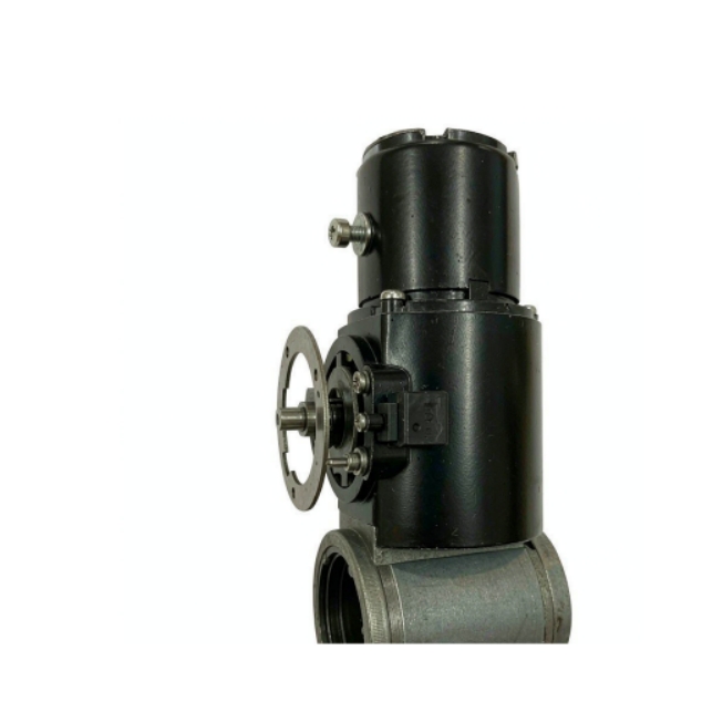
Close-up of a DC gear motor fitted with a magnetic encoder disc and Hall sensor on the rear shaft, on a white background.
What an encoder does not buy is mechanical accuracy. No sensor can remove the backlash sitting between the motor pinion and the output shaft, and no pulse count can compensate for gearbox hysteresis that is genuinely invisible from the motor shaft. That distinction — electronic resolution on one side, mechanical play on the other — is what decides whether feedback is worth its cost in your design.
This article covers what a Hall encoder measures, which problems feedback solves and which it leaves alone, and how to decide whether your application needs one.
What a Hall encoder adds to a gear motor
A Hall encoder is a rotary sensor that turns shaft rotation into electrical pulses. A small magnetised ring — normally mounted on the motor shaft, sometimes on the output shaft — rotates past one or more Hall-effect sensors, and each sensor produces a voltage transition as a magnetic pole passes it. Two sensors spaced a quarter of a magnetic period apart produce two square-wave channels, conventionally labelled A and B, whose pulse frequency is proportional to speed and whose phase order reveals direction of rotation.
From those two channels a controller derives three things: speed, from the pulse frequency; direction, from whether A leads B or B leads A; and incremental position, from counting edges. The signal is deliberately described as incremental rather than absolute — it reports how far the shaft has moved since the counter was last zeroed, not the shaft's absolute angle. That is why an incremental system is normally homed once at start-up, by driving the mechanism gently against a mechanical stop or onto a reference switch, and why the homing behaviour belongs in your specification as much as the pulse count does.
Because there is no contact and no optical path, a magnetic encoder adds no wear and tolerates dust and vibration, at the cost of resolution bounded by the magnet ring.
Hofon builds gear motors with Hall encoder feedback as an option across the DC gear motor range, which means the encoder is matched to the motor and gearbox at the factory rather than fitted afterwards as a loose accessory.
Resolution is not accuracy
The most common mistake in encoder selection is treating pulses per revolution as an accuracy figure. PPR describes how finely the drive can subdivide one revolution; it says nothing about how close the output shaft actually is to the angle that was commanded.
The error that matters is the sum of everything the encoder cannot see. If the sensor sits on the motor shaft, the count reflects motor rotation only, so gear backlash, tooth-to-tooth error and output bearing play are all invisible to it. If the sensor sits on the output shaft, the play between the output gear and the load is still invisible in the same way, because lash only appears when the direction of load reverses — the encoder sees a stationary shaft while the driven part is still moving through the gap. Resolution improves loop smoothness and speed regulation; it does not relocate mechanical error.
An illustrative calculation makes the split clear. A motor shaft turning at 6,000 rpm with a 32-pulse encoder generates 3,200 pulses per second, so the drive can regulate speed very finely indeed. But if the gearbox itself contributes a degree of backlash at the output, no software can close that degree — the counter will happily report a position the output shaft has not yet reached. Treat pulse count and backlash as two separate budgets, and remember that only one of them is electronic.
What feedback fixes, and what it cannot
Feedback pays for itself in a limited but well-defined set of problems:
·Speed regulation under varying load. Without feedback, output speed drifts as load, temperature and supply voltage change; with it, the drive trims duty to hold the target.
·Repeatable positioning between two or more points, provided the approach is always made from the same direction so that backlash is taken up consistently.
·Stall and jam detection. A stalled motor stops producing pulses, which the drive can detect in milliseconds instead of overheating the winding.
·Controlled deceleration and soft stopping, where the mechanism carries inertia or must not bang into its end stop.
·Motion profiling, including trapezoidal or S-curve profiles that need a position signal to generate.
It cannot touch a second set of problems:
·Backlash and gearbox hysteresis. Play between teeth is mechanical and cannot be measured away from the motor side of the gear train.
·Absolute position after a power interruption. An incremental encoder has no memory of where the shaft was, so the mechanism must be homed again unless a multi-turn scheme is added.
·Static holding against a load. Feedback reports that the shaft has moved; it does not create torque, so an unpowered gear motor can still be back-driven by gravity.
·Mechanical stiffness, torsional wind-up, or accuracy of the mounting interface — all downstream of anything an encoder can observe.
Problem | Does Hall encoder feedback solve it? | Why |
Speed varies with load or temperature | Yes | Closed loop trims duty to hold the target speed |
Position repeats within a known gap | Yes | Counter plus a single-direction approach takes up lash |
Stall or obstruction must be detected | Yes | Pulse train stops, which is a fast and reliable signal |
Gearbox backlash limits accuracy | No | Play sits between the sensor and the output shaft |
Absolute position after power loss | No | Incremental count is lost with the supply |
Holding a load with the drive disabled | No | Torque comes from energising the winding, not from sensing |
Hall or optical: which sensor suits the machine
Both sensor families are incremental rotary encoders, and both are selected against the same questions about environment, resolution and cost. The difference is the physical quantity being read, and therefore the failure mode you inherit.
A magnetic Hall encoder reads a magnet, so it tolerates dust, oil mist, humidity and shock, and it keeps working when a little contamination is unavoidable. Its resolution is bounded by magnetisation quality and channel count, which is usually ample for speed regulation and for positioning that already has a gearbox in the path. An optical encoder reads a patterned disc through a light path, so it offers finer resolution but requires a clean, sealed environment and gains nothing on a machine where gear play dominates the error budget. Where a gearbox is involved, paying for optical resolution is normally paying for detail the mechanism cannot deliver.
Deciding whether you need an encoder
Run the application against these statements. If two or more are true, feedback is very likely to pay for itself:
1. The mechanism must stop at more than one repeatable position, or return to the same position after each cycle.
2. Output speed has to stay within a stated band while the load varies across the cycle.
3. A jam or obstruction must be detected and reversed rather than stalled against.
4. The product has to report speed, position or travel distance back to a host controller.
5. Deceleration has to be profiled so that the mechanism does not slam into its end stop.
6. The load varies enough that an open-loop duty cycle cannot be set once and left alone.
7. Field behaviour has to be diagnosable, for example by comparing commanded travel with counted travel.
Wiring: four-wire and six-wire interfaces
An incremental Hall encoder is normally wired in one of two ways. A four-wire interface carries supply, ground and the two channel outputs, A and B, in single-ended form — the simplest arrangement and the one used wherever lead length is short and the electrical environment is reasonably quiet. A six-wire interface adds either a third channel that produces one index pulse per revolution, which gives the controller a repeatable reference point to home against, or differential output pairs that reject common-mode noise on longer harness runs.
The lead count is therefore a functional specification, not a purchasing detail. Confirm it, with the pin-out and the supply range, before the harness is designed.
Conclusion
A Hall encoder does not make a gear motor more accurate; it makes the drive able to see what the gear motor is doing, which is a different and more useful promise. Feedback buys speed regulation, repeatable positioning between points, jam detection and controlled deceleration. It cannot buy back backlash, absolute position after power loss, or holding torque when the winding is de-energised. Specify it only where it changes the outcome.
If you are weighing a gear motor with or without feedback, send the motion profile and the mounting drawing to Hofon and we will tell you which interface and pulse count the application needs — and where feedback would add cost without adding capability.