
How Does a Stepper Motor Work? Step by Step | Hofon
A stepper motor works by energising its stator phases in a fixed sequence rather than applying a continuous rotating field. Each change in that sequence pulls the rotor into a new alignment, so the shaft advances by one step angle per pulse and holds its position between pulses. The whole mechanism can be followed as one chain: a pulse reaches the driver, the driver energises a set of windings, the magnetic field inside the motor moves to a new direction, the rotor swings to align with it, and the output shaft moves by exactly one step.
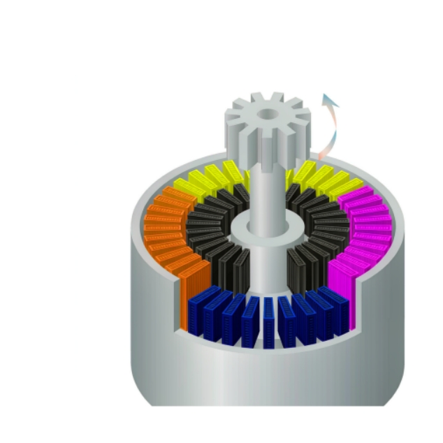
Cutaway illustration of a stepper motor with stator coils energised in sequence and the rotor advancing step by step, on a white background.
That chain is worth understanding in detail, because almost every stepper problem — lost steps, resonance, a motor that stalls only when the machine warms up — traces back to one specific link in it. This article walks the chain from pulse to shaft, explains how step angle follows from rotor construction, shows where full step, half step and microstepping differ, and sets out what actually limits the rate at which a stepper motor can be driven.
Hofon builds a stepper motor series with the step angle and frame size stated for each unit, which is the starting point for the sequence described below.
How the pulse sequence makes a stepper motor work
A two-phase bipolar stepper has two stator windings, conventionally called phase A and phase B, arranged so that their magnetic axes sit ninety electrical degrees apart. The driver does not energise both with arbitrary currents; it applies a repeating sequence in which each phase is driven in one direction, then off, then in the opposite direction. Because the two windings are offset, the resulting magnetic field steps round the stator in discrete increments rather than rotating smoothly.
The rotor — a permanent-magnet or variable-reluctance element with a toothed construction — has no field of its own that fights the sequence. It simply swings towards the nearest position in which its poles align with the field just created, and stops there, held in place by the field as long as the winding stays energised. That is why a stepper holds position without any feedback loop, and why it moves in steps rather than sliding continuously.
Sequence step | Phase A current | Phase B current | Rotor alignment | Shaft movement |
1 | Full, positive | Off | 0 electrical degrees | Positions at step 0 |
2 | Off | Full, positive | 90 electrical degrees | Advances one step |
3 | Full, negative | Off | 180 electrical degrees | Advances one step |
4 | Off | Full, negative | 270 electrical degrees | Advances one step |
5 (repeat 1) | Full, positive | Off | 360 electrical degrees | Returns to step 0 |
The table describes full-step operation of a two-phase bipolar motor. One complete cycle of the sequence moves the rotor through four steps, and the cycle repeats as long as the driver keeps clocking. Reverse the order of the sequence and the shaft turns the other way; stop clocking and the rotor stays where the last step put it.
Where the step angle comes from
Step angle is not a property of the driver. It is set by the interaction between the stator sequence and the number of teeth on the rotor, and it is fixed once the motor is built.
In a two-phase motor the rotor completes one full electrical cycle every four sequence steps, so the mechanical step angle is the electrical step divided by the number of rotor teeth. Multiply the step angle back out and you get the figure usually quoted on a datasheet: steps per revolution. The familiar 1.8 degree step comes from a rotor with fifty teeth; halve that to 0.9 degrees and you need one hundred teeth in the same frame. The frame does not get bigger — the teeth get finer — which is why the limit on step angle is manufacturing precision rather than motor size.
Two consequences follow. First, the rotor never rotates smoothly during a step; it accelerates towards the next stable alignment and settles, which is the source of the audible tick and the small overshoot that follows each pulse. Second, the position the rotor settles into is determined by the field direction, which means positional accuracy is bounded by the mechanical tolerances of the rotor and stator, not by the resolution of the driver.
Full step, half step and microstepping are the same mechanism
The three modes differ in how finely the current vector between the two phases is subdivided. The mechanism underneath — energise a field direction, let the rotor align — does not change.
·Full step. One or two phases are energised at full current, and the rotor settles at the four positions of the sequence. Highest torque per step, most audible motion, largest step angle.
·Half step. Single-phase and two-phase energisations alternate, so the rotor settles at eight positions per electrical cycle instead of four. Step angle halves and motion becomes smoother, at the cost of slightly uneven torque between the two types of step.
·Microstepping. Both phases are driven simultaneously with currents that follow sine and cosine so the field direction can be placed anywhere between the two windings. The rotor settles at a position proportional to the current ratio, so a 1.8 degree motor can be commanded in fractions of a degree.
Microstepping is often described as a resolution improvement, and mechanically that is what it is: finer field positioning. It does not improve the accuracy of the mechanical alignment, and holding torque per microstep falls away as the steps get smaller, because the rotor is being held by a smaller restoring force. Where the finer positioning matters — quiet motion, smooth low-speed running, avoiding resonance — it is worth having; where it is being used to claim better mechanical accuracy, it is not.
What limits how fast the sequence can be clocked
Nothing in the sequence itself sets a speed limit. The limit is electrical and mechanical, and it appears as a maximum step rate above which the rotor can no longer follow the field.
·Winding inductance. Current in a winding cannot rise instantly; the time constant set by winding inductance and drive voltage decides how quickly each phase reaches its commanded current. Drive a small motor from a low voltage and the current never gets there before the next step arrives.
·Back-EMF. As speed rises, the moving rotor induces a voltage that opposes the supply. Less net voltage remains to push current into the winding, so available torque falls with speed — the reason a torque-speed curve slopes downwards.
·Load torque and inertia. The rotor and everything attached to it must be accelerated from one step position to the next within the time the step allows. A load with high inertia, or a load that already demands most of the available torque, leaves nothing for acceleration.
·Resonance. Around certain step rates, the natural frequency of the rotor-and-load system is excited, and the oscillation grows until steps are dropped. Half stepping or microstepping changes the excitation frequency content and often moves the problem.
How steps are lost, mechanically
Step loss is not an electrical fault; it is a mechanical event. If the field moves to a new position faster than the rotor can follow, the rotor lags behind. As long as the lag stays inside the range of one step, the rotor still catches up and the position count remains correct. Once the lag exceeds roughly one full step, the rotor is closer to the next stable alignment in the sequence than to the one commanded, and it snaps forward — one step is lost, and from then on the commanded and actual positions differ by a fixed offset.
This is why a stepper system can run correctly for months and then fail once, at the moment a machine is operated slightly too fast, loaded slightly too heavily, or restarted before the grease has warmed up. The failure is a single event with a permanent offset, not a gradual drift, and it is why an open-loop stepper application either includes a homing routine or accepts that the position reference must be re-established after any suspected overload.
A stepper motor therefore works exactly as its name suggests — one pulse, one step — and everything that limits it comes from the physics of getting current into a winding and mass into motion before the next pulse arrives. Define the step angle and frame size first, then check that the drive voltage and the load allow the rate you need, and the sequence will hold up in production.
If you are matching a drive to a mechanism and want the sequence parameters checked against your load, contact us with your duty cycle and target step rate.