
What Is a DC Gear Motor? Geared DC Motor Explained | Hofon
A DC gear motor is a DC motor with a gearbox built onto its output — one assembly rather than two parts, in which the motor provides the rotational speed and the gearbox converts most of that speed into torque. The motor alone spins far faster than most mechanisms need and produces relatively little torque at the shaft; the gear train trades the excess speed for the force required to move the load. That single exchange is the whole purpose of a geared DC motor, and almost every other property — efficiency, backlash, noise, size, service life — is a consequence of how the exchange is made.
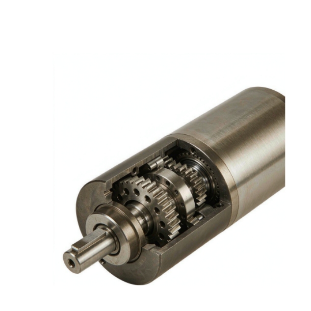
This guide covers what sits inside a DC gear motor, how the reduction ratio sets output speed and torque, how the three common gearbox types differ, and when a geared motor is the right answer.
Inside a DC gear motor: four functional parts
A DC gear motor is easier to reason about if you separate the functions rather than the components. Four of them matter:
·The gear train — two or more meshing stages that reduce speed and multiply torque. Stage count is what sets the achievable ratio, and each stage adds a little loss and a little backlash.
·The output shaft (or the final output stage) — the interface the mechanism actually couples to, and the part that carries the entire output torque and any radial or axial load applied to it.
·The bearings — one set supporting the motor rotor, another supporting the gear train and output shaft. Their specification normally decides the permissible side load and, in quiet applications, the audible noise floor.
·The housing and the gearbox enclosure — which fixes the gear centres, retains the lubricant, defines the mounting interface between motor and gearbox, and carries heat away from both.
Everything else — the brush assembly in a brushed motor, the controller in a brushless one, the magnets, the laminations — belongs to the motor half. When a datasheet quotes an output speed and torque for the assembly, it is quoting the result after the gear train, at one stated voltage and one stated ratio.
Hofon manufactures the DC gear motor range as an integrated assembly, which means the motor, gear ratio, output shaft and mounting interface are specified together instead of being matched by the customer after purchase.
Gear ratio, output speed and output torque
The reduction ratio is the single most important number in a geared motor, because it converts every figure quoted at the motor shaft into a figure at the output shaft. The relationships are simple enough to use as a design check:
·Output speed = motor speed ÷ reduction ratio. A motor turning at 12,000 rpm behind a 1:100 gearbox turns the output shaft at 120 rpm.
·Output torque = motor torque × reduction ratio × efficiency. The same gearbox multiplies torque by roughly one hundred before losses, which is why a small motor can move a load it could never move bare.
·Input power is conserved, less losses. Speed falls by the ratio and torque rises by it, so output power cannot exceed input power.
Two practical cautions follow from that arithmetic. The first is that efficiency is not a small correction at high ratios: each stage loses a few per cent, so a multi-stage reduction can give back noticeably less torque than the ratio alone suggests, and the figure has to come from the gearbox type rather than from the reduction number. The second is that the gearbox must be rated for the torque being asked of it — the motor torque multiplied by the ratio is the load the teeth see, and it is easy to specify a reduction that the gear train cannot carry.
Reduction is therefore a mechanical decision with a mechanical limit attached: the gearbox has to be rated for the torque the motor applies through it.
Spur, planetary and worm: how the three types differ
Almost all small geared DC motors use one of three gear arrangements, and each one trades something different.
Gearbox type | How it handles the reduction | Where it fits | Main cost of choosing it |
Spur (parallel shaft) | Simple tooth pairs on parallel shafts; one stage per gear pair | Straightforward reductions, cost-sensitive designs, higher output speeds | Longer body for the same ratio; more audible at speed |
Planetary | A sun gear drives planet gears inside a ring gear; several tooth contacts share the load | Compact, higher-torque, longer-life applications where length is limited | More parts; higher precision needed, so unit cost is higher |
Worm (right angle) | A worm screw drives a worm wheel, giving a large reduction in one stage | High ratios in one stage, right-angle layouts | Lower efficiency; suitability for continuous running has to be confirmed |
The choice is usually driven by the shape of the space rather than by the ratio, because all three can be built to reach a wide range of reductions. Planetary gearboxes are preferred where the envelope is short and the torque is high; spur gearboxes are preferred where cost matters and the layout is long; worm gearboxes are preferred where the output must turn through ninety degrees or where a very large ratio has to be achieved in a single stage.
Hofon builds planetary gear motors alongside spur and worm arrangements, so the gearbox type can be matched to the envelope and the duty instead of being fixed by what is available.
What a gear motor buys, and what it costs
The advantages of gearing are the mirror image of the costs, which is why the trade should be made explicitly:
·Low speed with high torque from a small, cheap motor — the core benefit, achieved without a separate reduction stage in the machine.
·Speed control by voltage or PWM, because the motor inside is an ordinary DC motor and the gearbox simply scales the result.
·Compactness compared with the alternative of a large direct-drive motor plus a belt or chain reduction.
·Predictable, fixed output speed for a given voltage, since the ratio is mechanical and does not drift.
The costs are equally predictable: efficiency is lost in the gear train, typically a few per cent per stage and substantially more in a worm reduction; backlash is introduced, so positioning accuracy is bounded by play rather than by the motor; noise appears at the tooth mesh, which matters far more in quiet products than in industrial ones; and the gear train becomes the life-limiting wear item, with lubricant and tooth loading setting the service interval.
None of those costs is a reason to avoid gearing. They are the reason a gear motor has to be specified against a duty cycle and a required life rather than chosen from a ratio table.
Gear motor or direct-drive DC motor?
A geared DC motor is not automatically the right answer. If the mechanism already needs a large reduction, if the output speed required is low, if the load needs holding against gravity, or if space is tight, gearing is usually the cleaner solution — one sealed assembly, one part number, one mounting interface, and a fixed ratio that cannot slip.
A direct-drive motor becomes the better answer when the mechanism needs high speed with modest torque, when it must be quiet and backlash-free, or when the reduction can be built into the mechanism — a belt, a leadscrew, a friction drive — more cheaply or more quietly than a gearbox can supply it. The deciding question is where the reduction belongs: inside a purchased assembly, or inside your own mechanism.
A third case deserves mention: a wide, continuously variable speed band. A geared motor holds the ratio fixed and varies speed by voltage or PWM, so it is most efficient at one operating point — a compromise to accept deliberately rather than discover on the test bench.
Where geared DC motors are used
Geared DC motors appear wherever a mechanism has to move slowly, carry a load and be built in volume. Office automation is the classic home for them — cash-handling equipment, printers, copiers, vending machinery — where paper or banknotes are transported at a controlled speed and stopped at a definite position. The same combination puts them in household appliances and building automation, in access and security hardware, and in production automation. The categories differ in duty cycle and noise limits far more than in motor technology.
Conclusion
A DC gear motor is simply a DC motor and a gearbox supplied as one assembly, so that the gear train trades speed for torque in a package designed to do it. The ratio converts motor speed and torque into output speed and torque; the gearbox type decides efficiency, backlash and noise; the duty cycle decides whether the assembly lasts. Specified in that order, a geared motor is predictable; specified from a ratio alone, it is a guess with a part number.
If you are working out whether a design needs a geared motor, send the load, the required output speed and the available space to Hofon and we will suggest a gearbox type and a reduction range rather than a single part number you then have to fit the application around.